The distance along a road (iron or tarmac) is referred to as the chainage, formally measured using a chain the length of a cricket pitch (22yards or 1/80th of a mile).
To calibrate the odometer of the dynamometer wagon, the raised level track of the Teesside Small Gauge Railway in Preston Park was surveyed with a metal tape measure and marks made every 99″, that is every eighth of a chain. The whole circuit was thereby measured as 16chains 65feet 3inches, although a mark was made 9″ further on to make a calibrated 17c.
The dyno wagon has a tone wheel with 31 slots in it attached to one of its axles. This is monitored with a light gate, thus making a square wave with 31 pulses per revolution. This is played into an input pin on an Arduino Teensy. Each edge of this square wave triggers a CAN message, which is sent to another Teensy for counting; the count being displayed on a slightly retro looking 8x7segment LED display.
Three circuits of the 17chain track were made and the counts recorded as 74770; 74788; 74741. These are all within 0.05% of their average.
The calibration therefore came out to be 0.1801″ per count. This puts the diameter of the wheels at 90.625mm which is close to the 90mm in the specification (plus a bit for the crud on the tyres).
Recalibrating the software, (with great thanks to the modern 32bit fixed point arithmetic) gives the display in chains, feet and inches.
The ground level track at Preston Park was thus measured from the platform to the loop, at 18c 46′ feet give or take half a fathom, whilst the raised level track at York was measured three times at 15c 61′ 0.0″ ; 15c 61′ 6.1″ and 15c 61′ 5.8″. Stopping at the same spot was tricky though so the 6″ may have been due to driver error.
In the midst of the heatwave, we have been running low on water for the garden and the occasional shower has not had much effect on the water barrel stocks.
To measure the level, I had in mind to use a Time of Flight laser range finder (such as the VL53LOX) which come nicely packaged on a PCB for arduino from ebay (£5.99 with free postage). This could be powered by a solar cell, read by an ESP32 (occasionally) and reported over the IoT wifi to an app on my mobile phone. I’d then be able to check the level from anywhere in the world.
Unfortunately I didn’t have one to hand.
I did however have a half full plastic tub of paint; a length of string, two pulleys and a nut splitter so in the space of half an hour or so knocked up a level gauge inspired by those on the side of water towers for steam trains.
Unfortunately I can only read it when standing next to it, but that is easier than getting my phone out, logging into wifi, finding the webpage…..
The miniature railway track at Roker Park in Sunderland has significant gradients as well as sinuous curves. This is a testing circuit for the novice driver of a 5″ gauge steam locomotive and I am also reliably informed, that the smaller the engine, the more difficult it is to keep it in steam.
Having spent a lifetime considering the dynamics of internal combustion, where on a modern diesel 100% power can be commanded in the blink of an eye, the dynamics of stoking the fire; injecting water; blowing draught and regulating the throttle; deserve a bit of consideration.
First the basics. A coal fire heats water under pressure that evaporates (and therefore cools) as steam is drawn off to drive the pistons. Because of the shape of the engine, air has to be forced through the grate and boiler using a vacuum in the smokebox under the chimney. This is achieved by steam being blasted up the chimney (perhaps the origin of the term funnel), either from the exhaust from the pistons or from a blower of steam from the boiler.
A steam blower in the chimney draws air through the fire.Smokebox below funnel.
The water in the boiler has to be replaced by either an axle driven pump, when the engine is moving, or an injector which is a sort of solid state pump driven by a steam jet.
An axle pump injects water into the boiler when the engine is in motion. A steam jet can also be used to inject water when there is enough pressure in the boiler.
The fire, of course burns coal (carbon) which has to be replenished through stoking. The heat of combustion of coal is about 14,000 BTU/lb (32.5MJ/Kg). So an 1/8 oz lump of coal should heat 5lb of water by about 125 degrees Fareinheit. Or boil 100oz of water. It’s not that efficient though.
The principal dynamic states of the machine are therefore the volume, temperature and pressure of water in the boiler, the mass and temperature of the fire, and of course the speed of the train. The air supply is pretty immediate to respond, as is the delivery of torque from the regulator.
The relationships between the inputs and the states are:
The mass of the fire is obviously the integral of the stoking less the carbon burnt off.
The heat generated by the fire is the rate of carbon being burnt off.
The temperature of the fire is the integral of the heat given off from combustion less the heat supplied to the boiler and the heat required to heat the fresh coal put on. All divided by the mass of the fire and grate.
The combustion heat is probably proportional to the air drawn through, provided the temperature is above a certain level meaning that all the O2 is burnt to CO2.
This flow of air is related to the blast from the blower and the exhaust steam. These of course relate to the power delivered to the train and the blower valve setting in relation to the boiler pressure.
There is an effect of the fire door being open and a cold draught being drawn along the boiler tubes in place of hot flue gasses, this is complicated. So is the constriction of the air by the fire; coal and clinker which is melted impurities forming an impervious but brittle sheet over the grate.
The rate of change of the temperature of the boiler water will be related to the heat supplied, the flow of cold water into it and the cooling of the evaporation. There is also the heat lost through the lagging or lack of it.
All this has unstable operating reigons. If the fire is good and the blower left open, thermal runaway occurs as the boiler pressure builds, air flow builds and the fire heats. Only the safety valves blowing off prevents explosion, and then some form of melt down might occur when the boiler boils dry.
It is possible to install a controlled blower valve that shuts off if boiler pressure raises sufficiently, but I have only seen one in 7.1/4″ gauge.
On the other hand, if boiler pressure drops below the point where the blower can sustain the fire, the fire goes out. Only by using another draughting method (an electric vacuum pump on the chimney is used to light the fire and heat the boiler up in the first place) can the fire be re-lit.
I’m sure all this could be put into mathematics and a control system developed. I would start with a feedback control of draft or smokebox vacuum, using the blower, to maintain temperature / pressure in the boiler. Also a feedback control of coal level in the fire, with some sort of feedforward to blow more air to heat the fire as extra coal is put on. The water level would be maintained closed loop against the disturbance of evaporation to the pistons or the blower (or safety valves) by switching on / off the injector, with again a feedforward element to the blower / air supply to add heat to the cold water.
Speed control of the train would be by control of the regulator / throttle. In my case the cut off doesn’t really work like it would on a big train where the regulator can allegedly be left open and speed controlled by adjusting the valve opening times, thus achieving more efficient use of the steam expansion in the pistons.
The timing of the pistons’ valves can be adjusted from full forward to full reverse. The intermediate settings allow limited output power on wide open throttle. But not on my engine.
On the Sunderland track a friction brake on the train helps, and, as can be seen at the end of the video, it is best to maintain tension in the three link chain coupling between the engine and the train.
Nowadays, this sort of control design is too complicated to code, and some sort of Python library running on a Java engine would perhaps be used to train an artificial intelligence system by supervised learning. Which is a possibly a bit like how the enginemen of old learnt to drive a hundred years ago.
After a few years of hard work, the cheap and formally cheerful lawnmower decided it wanted to be put out to grass and packed up.
Before it headed to the great lawnmower rest home in the tip, I decided to fulfill its wish of donating its body to science and took a P2 screwdriver and a 13mm spanner to it.
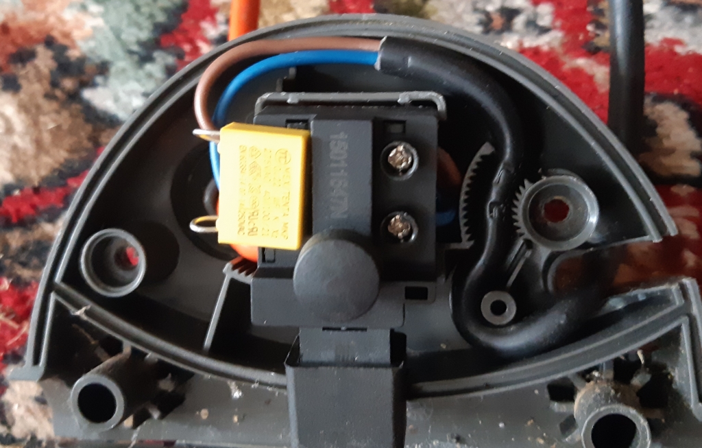
The insides showed the ravages of many years of grazing but with a bit of a vacuum and brush up the brushes seemed fine and the wiring sound.
The finger of suspicion then turned to the switch and a few prods with a continuity detector found a non conducting but otherwise sound looking neutral wire.
It seems that mid insulation, a break had burnt through.
With the break cut out, the continuity was restored and many more years of happy mowing is anticipated.
Inspired by a conversation about boiler water treatment; with a retired water treatment engineer, I splashed out the princely sum of £6.51 (including postage) on a “Electric Digital TDS*&EC Meter Tester”. These are some of the results of various waters.
Tapwater 137ppm.Filtered and boiled tapwater 132ppm.Waterbarrel from concrete roof 55ppm.Rainwater from Aluminium Greenhouse 16ppm.River water at Stokesley (including duck food) 235ppm.Pond Water (including duckweed and frogspawn) 157ppm
Clearly the greenhouse water is the one to use in the steam engine.
To validate the conical wheel stabilty (mathematical) model I turned the system engineering paradigm of : requirements capture; targets cascade and components design intent on it’s head and searched for the biggest lump of something I could turn in the lathe.
A forray round the estate unearthed the following.
A large log of elm that someone without the heart to burn it had given me about five years ago and has been in the garden ever since.
A leg off an (Ikea?) table made of oak blocks glued together.
A lump of redwood that had hung down as part of he bannisters until it got in the way of the front door curtain.
Starting with the last, it was slowly rounded off to 3.3/4″ in diameter by 6″ long.
at this point it would fit over the saddle in the lathe and with the cross slide set over by 5.7 degrees the ends were taken down to a 1:10 taper. This gave a 3.1/32″ end diameter and a 3.5/8″ centre for a 6″ long barrel. Applying this to a 5″ gauge track should give a wavelength of 39″.
The sleepers on this test track are 3.1/4″ apart and from freeze frame images the wavelength can be seen to be 12 sleepers or 39″
Sleeper 17 : Displaced to its left.Sleeper 11 : Displaced to its rightSleeper 5: Displaced to its left again.
[a longer video of the barrel on a 3.1/2″ gauge track is on youtube]
The leg from the Ikea table was similarly turned down to a 12″ long spindle, 2″ diameter in the centre and with a 1:20 (2.87 degree) cone angle. This giving a 1.400″ diameter at each end.
On 5″ track, this should give a wavelength of 41.5″
Sleeper 17: Displaced to its left.Sleeper 11: Displaced to its right.Sleeper 4.1/2 : Displaced to its left again.
This shows the wavelength to be 12.1/2 x 3.1/4 or 40.3/8″
In my early teens I was subjected to several inspirational moments at my excellent secondary school. One such moment was in a geography class learning about out the rain cycle of the Amazon forest. I had stuck a circular rubber on the end of a round pencil and was rolling it around the desk, noting how it described circle. Despite the distraction of a sarcastic teacher implying that engineering would be of no use without a geography O level I found the moment an enlightening insight into the wonderful world of conics. The geography O level I subsequently got, conversely, has been of no use whatsoever.
A railway wagon, as I’m sure you will know, glides along the track due to to the conical shape of both wheels. The flanges are there only as a last ditch attempt to keep the train on the track in the case of something going badly wrong.
With both wheels rigidly attached to each other they revolve at the same speed but the distance covered changes slightly due to any difference in their diameter.
The wheels are machined so that the outer edge diameter is slightly less than the inner. Consequently if the wheelset is displaced to the left, the left wheel moves further than the right, which has a tendency to steer the axle to the right. Once turned to the right however the axle will overshoot the halfway until the right wheel is larger than the left and the axle turns to the left once again. This can all be described mathematically.
Consider the cone angle to be, say, 1:20 that is for each inch the wheel is displaced outwards on the track the radius is 1/20″ larger. Then if R is the nominal wheel radius and x is the displacement of the wheelset (to the right), then the radius of the left wheel can be described as and the radius of the right where k is the cone angle, 1/20 in this case. Since the track and wheels may not be perfectly nominally sized we can only consider the difference, but that is all that is important in this case.
The tendency for the axle to steer can be described using the concept of the angle the axle has to the direction of the rails. Consider this to be , measured, of course, in radians and such that a positive angle is the axle steering to the right.
The change in as the wheel rolls through a small angle, let us call it is determined by the difference in wheel radii. The left wheel will move forward by and the right by The difference being . A positive difference is when the right wheel is bigger than the left.
This steers the axle (in yaw) so that the angle is changed by the difference in progression of the two wheels, divided by G the distance between them (the gauge of the track). We can describe this as the change which is or . Note that a negative has crept in since if the right wheel is bigger, x is positive, the axle steers to the left.
Finally we have the change in x being related to the angle the axle is pointing . If the wheel rolls forward by it will move to the side by this times the angle it is pointing. Hence
Now we can eliminate some of the variables and show
and
This is one of those ‘the rate of change of the rate of change of a something is the negative of the something in the first place’ relations. It can only be satisfied by a sinewave whose rate of change of rate of change of is the opposite of the sinewave.
Looking at the rate of change of the rate of change of x this is R times the rate of change of which is
Hence the displacement of the axle on the track, x is a sinewave of period (in , the angular rotation of the wheel) of since this satisfies
Note that the amplitude of the oscillation is irrelevant. It neither grows or diminishes with progression down the track. Whatever it starts with it continues with and so the stability is said to be marginal.
With this relationship it is possible to establish the ‘wavelength’ or distance along the track between one extreme excursion and the next. This will be when or
For the case of a 3″ wheel on a 5″ track, with a cone angle of 1/10 this should be or about 25 (radians). With the wheels 1.5″ in radius, this is therefore about a yard.
The saga of the wagon wheels continues with the appearance of some iron castings. These were baked in the coal fire and the skin taken off before an attempt at shrink fitting to the axles.
My calculations on how much a 1/2″ hole dilates with temperature estimated 0.0009″ over 200 degrees. Cooking the wheels at 200C for 20mins gave a growth of 3.711″ to 3.718″ which is an expansivity of 9.41/MK
A hole was machined to 0.4995-0.500″ using the ‘setting of the cross-slide to 5.7/2 degrees’ method, so 10thou advancement reduced diameter by 1thou, and the axle reduced to 0.5007″ as measured on a vernier screw micrometer… or near as I could.
Then with oven gloves and bated breath, the wheel was dropped on to a slightly thinner end section and jammed immediately. This heated the axle up a treat and nothing moved further without a hammer. Clearly the idea only works with the two parts thermally isolated from each other until in position.
The thermal expansivity of steel is only a bit more than iron so going the other way to get a sliding fit to warm up tight would involve cryogenics.
Meanwhile the word on the web was that LBSC had recommended a 1/2-5/8 thou oversize axle for pressing on. The axle was duly turned at the end to be a tight push fit then a half thou added for the bit upto the shoulder. The first attempt worked OK in the hydraulic press but the second axle was a bit too fat and bent both itself and the press before it jammed.
This duff axle was therefore hacksawed in half and pressed out of the wheels and a new axle made which this time was pressed in successfully.
After a bit of a rust-up in the garden, the winter snow helped, the profile was finished between centres and the ends trimmed with a fixed steady.
In the depths of the garage are still several cardboard boxes we packed when we moved house. Now, opening them up again, several years later, treasures appear like Christmas morning all over again.
One such treasure was a lightbox, made when microchip were touting their 40 pin microcontrollers that you coud still see (and erase) through a glass window, and before Arduino had cornered the tacky hobby software market.
The box consists of sixteen lights between the seventeen stations from Middlesbrough to Whitby, each a 12V car dashboard warning lamp stripped of its holder, and driven off 8V or so to give a soft start and dim glow.
The lamps follow, in real time, the progress of trains on the line, according to the timetable sometime about the turn of the centuary (the most recent one).
I used to have it in the kitchen, powered from the burglar alarm 12V supply, as a sort of alarm clock to prompt me to leave the house for work — for example ahead of the train getting to Battersby.
Having lost the sourcecode, I can’t remember how to set it, which I think involved powering it up at midnight; perhaps on a Sunday to set the daily variations. I do remember it didn’t keep very good time, so the ‘going to work on time’ didn’t quite go to plan. After a week or two the trains were all over the place with respect to the timetable.
There is something remarkably pleasing about steam (or I suppose compressed air) reciprocating motive power particularly at the singularity which is zero speed.
I reminded of a situation where a large steampowered omnibus was waiting to ascend a very steep hill at Whitby. Expecting a huge drama of billowing smoke and overheating clutches I was amazed to watch the bus driver simply release the handbrake and the bus rolling up the hill in just the way, to quote Douglas Adams, that 11 tonnes of cast-iron and mahogany, doesn’t.
Similarly for the demonstration of a shunting manouvre with a J27 on North Tyneside. We have become so used to mechanical movement involving 40 explosions per second* that stealth is now an issue to us. Electric cars may be a new problem, but at least we don’t have to worry about big cats or sabre toothed tigers stalking us any more.
* 1200 rpm is 20 revolutions per second. A 4 cylinder 4 stroke engine will therefore have 40 power strokes in one second.


 and the radius of the right
  where k is the cone angle, 1/20 in this case. Since the track and wheels may not be perfectly nominally sized we can only consider the difference, but that is all that is important in this case.

 , measured, of course, in radians and such that a positive angle is the axle steering to the right.
 is determined by the difference in wheel radii. The left wheel will move forward by
  and the right by
  The difference being
  . A positive difference is when the right wheel is bigger than the left.
 which is
  or
or  . Note that a negative has crept in since if the right wheel is bigger, x is positive, the axle steers to the left.
 it will move to the side by this times the angle it is pointing. Hence


 , the angular rotation of the wheel) of
  since this satisfies


 or
or 
 or about 25 (radians). With the wheels 1.5″ in radius, this is therefore about a yard.


